Free body diagrams
A free body diagram includes a complete or part of a model, with all loads acting on that part, including support reactions. It can also include dimensions and coordinate system(s).
Free body diagram of entire model
A free body diagram of an entire model doesn’t show section forces.
An example model is shown in Figure 1.
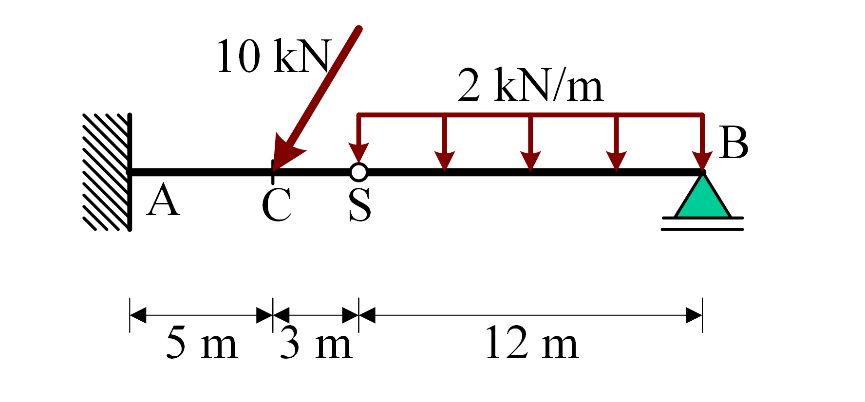
Figure 1:Example model
The free body diagram of the entire example model is shown in Figure 2.
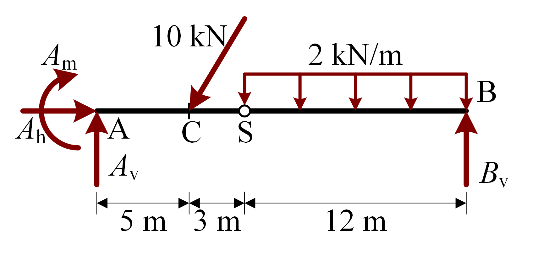
Figure 2:Free body diagram of the entire example model
Free body diagram of a hinged part of a model
In the free body diagram of a hinged part of a model, a cut is made at the hinge, showing the (potential) interaction forces at the hinge.
The free body diagram of the right hinged part of the example model is shown in Figure 3.
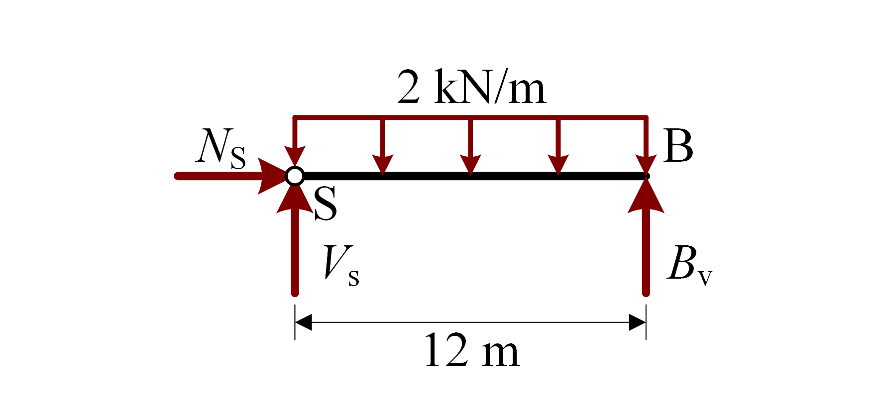
Figure 3:Free body diagram of the right hinged part of the example model
Free body diagram of a part of a model
In the free body diagram of a part of a model, a cut is made at the any arbitrary point, showing the (potential) section forces in the elements.
The free body diagram to the right of a cut just left of point of the example model is shown in Figure 4.
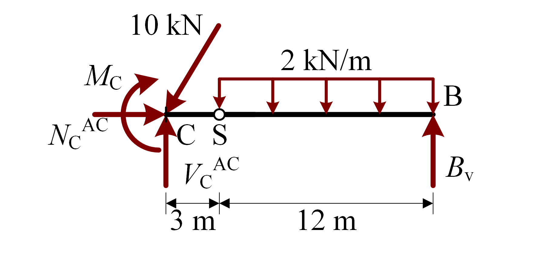
Figure 4:Free body diagram to the right of a cut just left of point of the example model
A cut can also be made such that only a single point is left. In that case you can draw the free body diagram of this single point.
The free body diagram of point of the example model is shown in Figure 5

Figure 5:Free body diagram of point of the example model
Alternatively, a small part of the connected elements is drawn to indicate the direction of those elements.